For all the definitions below, means the number of turns.
Self inductance
Section titled “Self inductance”When the magnetic field produced by a coil causes an emf on itself. Denoted by . Measured in henry ().
For a coil having self inductance, turns, carrying current , the generated is given by:
Mutual coupling
Section titled “Mutual coupling”Mutual coupling between coils exist when one (secondary coil) is in the magnetic field created by the other coil (primary coil).
When a time-varying current flows in the primary coil, a time-varying flux is produced, which produces a back emf .
Magnetic field
Section titled “Magnetic field”Magnetic flux density
Section titled “Magnetic flux density”Measure of strength and direction of the magnetic field. Denoted by . Measured in tesla () or or .
Magnetic flux
Section titled “Magnetic flux”Denoted by . Measured in weber ().
Magnetic field strength
Section titled “Magnetic field strength”Aka. magnetic field intensity. Denoted by . Measured in ampere per meter ().
Magnetic permeability
Section titled “Magnetic permeability”Measure of magnetization on a material when a magnetic field is applied. Depends on the material. Denoted by . Measured in or .
Flux linkage
Section titled “Flux linkage”Denoted by . Defines the interaction of a multi-turn inductor with a magnetic flux.
Magnetomotive force
Section titled “Magnetomotive force”A force acted on a coil carrying current. Denoted by .
Here:
- - number of turns
- - current in the coil
It’s similar to electromotive force in electrical circuits.
Reluctance
Section titled “Reluctance”Reluctance of a path for magnetic flux:
Here:
- - Length of the path
- - Permeability
- - Cross-sectional area
The above equation can be thought of the equation of resistance in electrical context. is used instead of .
is similar to in electrical context.
Fringing
Section titled “Fringing”Flux lines in the air gap tend to bow out. Thus the effective area of air gap is larger than the cross sectional area of the core.
Faraday’s Law
Section titled “Faraday’s Law”The magnetic flux passing through a surface is given by the surface integral:
Ampere’s Law
Section titled “Ampere’s Law”Line integral of magnetic field intensity around a closed path is equal to the sum of the currents owing through the surface bounded by the path.
When is constant (magnitude and direction) along the path, the above equation reduces to .
When is constant and the path has turns, .
Mutual inductance
Section titled “Mutual inductance”When 2 coils are coupled, part of the magnetic flux produced in the primary coil links with secondary coil.
Coefficient of coupling
Section titled “Coefficient of coupling”Ratio between the produced magnetic flux and linked magnetic flux. Denoted by .
Induced emf
Section titled “Induced emf”Since the produced flux is time-varying, an emf is induced in the second coil.
In the linear region of magnetization characteristic:
Here is the mutual inductance.
Practically, coupling between the primary and secondary coils is identical to the coupling between secondary and primary coils.
Energy stored
Section titled “Energy stored”The last component is the effective energy stored in the mutual inductance.
The mutual inductance energy is:
- Added; if produced fluxes aid each other
- Subtracted; if produced fluxes oppose each other
Equivalent inductance
Section titled “Equivalent inductance”In series
Section titled “In series”The mutual inductance is:
- Added; if produced fluxes aid each other
- Subtracted; if produced fluxes oppose each other
In parallel
Section titled “In parallel”The mutual inductance in the denominator is:
- Subtracted; if produced fluxes aid each other
- Added; if produced fluxes oppose each other
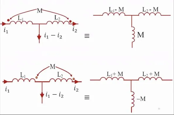
T-junction
Section titled “T-junction”If 2 coils are given in a T-junction, the circuit has to be changed to include a 3rd inductor. If the coils were aiding, the 3rd inductor will be , otherwise . The 3rd inductor value will be subtracted from the other 2 inductors.
Dot notation
Section titled “Dot notation”One terminal of the coils is marked with a dot. If both currents enter or exit from the dotted terminals, the fields aid; mutual inductance is positive. Otherwise the fields oppose; mutual inductance is negative.