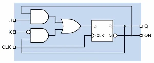
Has 2 inputs: and , and 1 output: . Extension of SR flip-flop. Eliminates the invalid state of SR flip-flop.
Widely used in digital systems for counters, shift registers, and other applications where toggling or controlled state changes are required.
Characteristics
Section titled “Characteristics”Characteristic table
Section titled “Characteristic table”| J | K | Operation |
|---|---|---|
| 0 | 0 | No change |
| 0 | 1 | Reset |
| 1 | 0 | Set |
| 1 | 1 | Toggle |
Excitation table
Section titled “Excitation table”| Current State (Q) | Next State (Q+) | J | K |
|---|---|---|---|
| 0 | 0 | 0 | X |
| 0 | 1 | 1 | X |
| 1 | 0 | X | 1 |
| 1 | 1 | X | 0 |
Implementation
Section titled “Implementation”Using D Flip Flop
Section titled “Using D Flip Flop”